Object-oriented programming started in the 1960’s with Simula, it was followed by Smalltalk and later by C++ and Java. Object-oriented programming promotes coding in ways that were not possible with procedural programming, allowing for more maintainable projects. Agile programming is also really old. Scrum started in the 1980s and extreme programming and other variants started in the 1990s. However, the important moment for agile development was in 2001 when the Agile Manifesto was written.
Agile development works really well for large scale projects. However, agile development can be misused the same way object-oriented programming can. Just because you are using an object-oriented program doesn’t mean that you are using an object-oriented approach. In the same way, just because you are having regular meetings and stand ups doesn’t mean that you are doing agile development. The procedure has to be done right if you want to reap the benefits of agile.
One flavor of agile development is extreme programming, which focuses on small, iterative and frequent releases throughout the whole process. Extreme programming is based on five core values.
Simplicity: we will only do what was asked for, nothing more. This will greatly reduce the complexity of the project.
Communication: the members of the team interact face-to-face and have meeting regularly.
Feedback: since new releases are being made constantly, the feedback from these releases must be used to improve the project as a whole. The team will adapt to this feedback, even if large changes are needed.
Respect: every member of the team is important and deserves respect. Even the customer deserves respect.
Courage: the truth will always be told regarding estimates of cost and time. Also, there will be no excuses for failure.
The general process and flow of extreme programming can be seen in the following image.
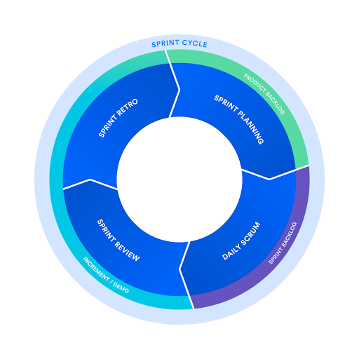
Another flavor of agile is Scrum, which aims to add new functionalities to the software every 2-4 weeks. One of the main reasons to use scrum is because information is transparent, team members can acapt based on current conditions rather than predicted conditions. Also, Scrum is very scalable, more so than other agile development variations.
Object-oriented is closely related to agile development since they both break down the project into smaller parts. With agile, you will be able to release prototypes constantly and get feedback from them. There are many flavors of agile and some of them may adapt more easily to your project.
Test-driven development (TDD) is a development process that occurs in very short cycles. All the requirements are expressed as test cases and the software is changed until those test cases are passed. The goal of TDD is to write clean code that works. TDD follows a cycle.
Tests are added.
You see how the tests fail with the current code.
Code is written with the purpose of passing the tests.
After the last step, you go back to step one and repeat the whole process again, but with a different test. If a test fails, you need to go back to step three to make the necessary changes. The final refactor stage is really important, in step three you just want the tests to pass, even if the code isn’t pretty. In the last step, you are allowed to change the code as long as its functionality stays the same, the code is brought to a professional level.
Before adding anything to the code, a test has to be passed. This means that our code will always be functional.
Before adding a new functionality to your code, you need to write a test. Tests should have an expected outcome in order to know if you passed it or not. Thanks to this, every new functionality will have a clear outcome.
Every test must be completed by itself, without relying on other tests. You need to think about how the different parts of the code are connected, leading to a more modular project.
TDD, while in theory, should work with every language, it will work better when using object-oriented languages. TDD relies on tests that small chunks of code have to pass, object-oriented languages are good at dividing code into small parts and having each of these parts be independent. Being able to divide the code into classes and each class has to pass a test will make the whole process easier.
TDD will enable you to reduce future bugs in your project significantly. Ensuring that every part of the code works perfectly is a powerful asset for TDD. Also, since you are trying to make every test independent, another test shouldn’t break past tests. TDD is a powerful tool that I haven’t used that much personally, but I can see the value in it. I will probably end up using in the future given how convenient it is.
When working with an object-oriented system, object-oriented testing is preferred, conventional testing strategies may yield less desired results. Object-oriented testing revolves around the concept of classes. There are three main types of object-oriented testing: class testing, inter-class testing and system testing.
Class testing: this type of tests include unit testing, which was already discussed in a previous blog. With class testing, every class is tested independently of others. If the class need certain types of input from another class, the input is generated by the tester and the output is verified. With class testing, you are sure that the tested lass is free of bugs and errors.
Inter-class testing: with this type, various classes are joined into a module or sub-system. What’s being tested is the coordination between the classes in the module.
System testing: the whole system is tested. Everything should work as expected. Things like performance, reliability and usability are also tested.
When working with and object-oriented program, you can take advantage of the many qualities that come with object-oriented programming. When working with a different paradigm, dividing the code into independent units may not be possible and other types of testing will be needed. I have used this before. Just testing a class without kinking it to another one to see if it works. You will need to generate the input yourself since there will be no class to generate it, but it can help identify in which class there’s an error if your program isn’t working.
When developing software, verification and validation serve the purpose of verifying if the software meets the specified requirements and if the software is fulfilling its purpose. Doing verification and validation can help us answer some key questions: “Was this software what we should have built? Assuming we build this software, will we be able to achieve our goal?”. There’s an IEEE Standard for Software Verification and Validation. This standard provides common frameworks when working with V&V processes.
Verification can be defined by “Are we building the product right?”. Verification is done before the implementation starts. Verification includes checking that the proposed system will solve the problem without bugs or errors. We are trying to see if the project aligns with the requirements before even starting it. During the verification phase, there are a couple of steps that are involved: inspections, reviews, walkthroughs and desk-checking.
Validation can be defined by “Are we building the right product?”. Validation is done after the implementation is done. Validation evaluates the project and determines if the project satisfies the requirements. It’s useful to ensure that the project meets the user’s needs, the project works as intended. Validation includes various activities, which are all types of testing: black box testing, white box testing, unit testing and integration testing. The phases in which verification and validation happen can be seen below, a V model is used.
One of the activities that is part of verification are walkthroughs. Walkthroughs includes reviewing documents with peers and managers, generally, everyone that participates in a walkthrough works in the same project. During the walkthrough, the author of the document is who guides others through the review. On the other hand, one of the activities that’s part of validation is unit testing. This type of testing involves taking parts or components of the code and testing them separately. These units may receive an input and return an output, as long as this output is correct, that unit is working properly. When working with an object-oriented language, a unit can be a method.
Validation and verification are really useful, they ensure that you don’t do a lot of work that you end up not needing. I have personally suffered a lot thanks to not doing this. There have been times where I start a project and need to start all over again because what I did was fundamentally wrong, the project didn’t really fulfill the requirements.
For code revision, I will first talk briefly talk about some of the best practices when doing code review and then talk about personal experience with this topic. Let’s start by defining what is code review. Code review is when one or more people check a program you wrote by reading parts of it. The reviewers help find defects with the code and find better solutions to the problems the code is trying to solve.
Some good practices are important to get the most out of code reviews. First, don’t review too much code at once. Second, don’t rush the review, reviewing 500 lines of code should take about an hour. Third, the review shouldn’t really take more than an hour, meaning that you shouldn’t be reviewing more than 500 lines of code at a time. Fourth, it is very important to set goals before starting a code review, you need to know how you will measure the effectiveness of the code. Lastly, always do code review with a positive attitude. Getting all your mistakes pointed out by your peers may not be the most pleasant thing, but it needs to be done. There are many more ways to improve your experience with code reviews, but the tips given here should give you a good idea of what to do.
Now I will go over my experiences with code reviews in the past. Last summer, I had the opportunity to do an internship at a software company. Code reviews were a part of the internship and they really helped me, but I can understand why it’s possible to find code reviews frustrating at times. My experience with code reviews is an interesting one. The first code review I experiences were really helpful. I was working on Android development for the first time, so there were some best practices that I didn’t implement. Those got pointed out to me and I fixed them. After that, I didn’t make the same mistakes again. Later in the internship, I came across quite a big problem with my code. The code reviews slowly, but surely helped me. What happened was that I had an error in my code and it was pointed out. I tried to fix it, however, it turned out that the way I fixed wasn’t really fixing it, well, it fixed the error, but created more. This happened a few times until I was able to reach the correct solutions. I think the problem was my attitude towards the code reviews, even though they helped me, they could have helped me even more if I followed the core review best practices.
Code reviews are a powerful weapon if it’s in the right hands. A bad attitude can cause the collaboration between team members to worsen. Moreover, doing too much at a time during code reviews can actually reduce the chance of finding defects in your code. A good code review will drastically increase your code quality.
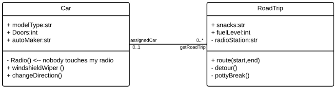
After doing design, you may end up with a class diagram. When the implementation part of a project begins you will have to code those classes. There are certain techniques that make mapping a diagram to code easier. This significantly improves the speed at which implementation happens. I will illustrate this using an example. The example will be using Java.
First, let’s start with the Car class. First, the attributes are easy enough to code. The + or – at the left of the attributes tells us if the attribute is public or private, + is public and – is private. After the sign, there’s the attribute name and the type. For the Car class, the attributes will be as follows:
public String modelType;
public int Doors;
public String autoMaker;
For the methods, you just have to write the name, if the method has arguments, the arguments should also be written in the code. After the name of the method, the return type may be defined. If the method takes arguments, the type must be inferred. Of course, the body of the method isn’t defined, the developer will have to do that himself. For the Car class, the method will be as follows:
private void Radio() {}
public void windshieldWiper() {}
public void changeDirection() {}
The last part is mapping the relationship between the classes. In this case, the cardinality of the relationship is what’s important. For the Car class, the relationship getRoadTrip will turn into a method. The return type of the method is the receiving class, RoadTrip. The cardinality defines if the method returns one object or an array of objects. If the cardinality is 1, it returns an object and if the cardinality is *, it returns an array. The method will be as follows:
RoadTrip[] getRoadTrip() {}
Following these rules, the RoadTrip class will be as follows:
public String snacks;
public int fuelLevel;
private String radioStation;
public void route(int start, int end) {}
private void detour() {}
private void pottyBreak() {}
Car assignedCar() {}
The language choice matters here. Ideally, you will want to choose an object-oriented language. It is possible to depict objects without using classes, but it’s a bit more complicated. You will mainly want to do this if the language offers something that object-oriented languages can’t. This an example of how to depict an object in Python without using classes.
Knowing how to properly map a diagram to code can greatly speed up the implementing process. Sure, the implementation of the methods isn’t included in the diagram, but the structure of the code is mostly done. This type of mapping can simplify a developer’s work.
Many modern businesses use programming languages like Java or C# to build applications and use a relational database to store the needed data. There are other options, but object-oriented technologies and relational databases are the norm. To store classes in a relational database, it is necessary to to a class to table conversion.
The first step when doing this conversion is to look at the attributes of the class. All attributes are mapped to zero or more columns in a database. An example of an attribute that won’t be stored in a database is your age (if you are already storing your date of birth your age can be calculated using that) or the average grade of a student (if you have the grade of all the courses, the average can be calculated without the need to store it). If an attribute of an object is another object, there will be an association between these two objects and the second object will have its attributes mapped. This is done recursively until you obtain an attribute that maps to zero or more columns.
However, mapping a class to a table isn’t always so easy. Inheritance is something that can complicate mapping quite a bit. How do you map correctly inherited attributes? When dealing with inheritance there are multiple techniques you can use to successfully map it.
The first approach is to map the whole hierarchy to a table. You will probably end up with huge tables, but it works. The next approach is for each concrete class to have its own table. For example, if you have three classes, user, student and teacher, and both student and teacher inherit from user, you will create two tables for student and teacher. Each of the tables will have both the attributes of that class and the attributes of the user class, in the previous approach, it would all have been just a big table. And the last approach I will talk about in this post is mapping each class to one table. Using the previous example, there will be three tables instead of two, one for each class. The way student and teacher will inherit the attributes is by having a foreign key that points to the user table.
Another thing that can be difficult to map are relationships between classes. A few key points are that if a class has a getter method, that class probably has a one-to-one or a one-to-many relationship with the class the getter is getting from. For example, if you have an Employee class that has an attribute of type Department (Department is another class), the getter method that returns the department will always return only one value. However, different employees may return the same department from the getter method, this means that there is a one-to-many relationship between Employee and Department. If every employee returned a different department, the relationship would be one-to-one. Another key for defining relationships are arrays. If a class has an array whose type is another class, that would mean that the multiplicity of that class in that relationship is 0..* or 0..1. Whether this relationship is one-to-many or many-to-many, it all depends on the other class and how it is related to the original class.
I have never worked with non-relational databases, but, from what I gathered, it’s still possible to do the mapping. The most basic case is simple, each field name maps to one object attribute name. Next, there are embedded values, which are used for collections, the @Embedded annotation. For relationships, annotations are also used (@OneToOne, @OneToMany, @ManyToMany, etc.).
Most modern businesses use object-oriented technologies together with relational databases. Given that this is the norm, mapping classes to tables becomes an important part for many businesses. It may turn out to be more difficult depending on your system, but the mapping can be done.
Unified Modeling Language (UML) is a general-purpose modeling language. The purpose of UML is to define a standard way to visualize a system and its design. A good analogy for understanding UML would be to think of it as if it were the blueprints of a house, but instead, the blueprints of s system. UML is not a programming language, but rather a set of rules of how to represent a system visually. Using UML makes the system easier to understand for engineers, businessmen and system architects. The following video explains UML very well.
Now, a bit of history of UML. During the 1970s and 1980s, object-oriented modeling languages were starting to emerge, but weren’t numerous yet. However, after that until the end of the decade, the number of object-oriented modeling languages exploded. In 1996, from this huge number of modeling languages, UML was created. UML was created by merging Booch, OOSE and OMT. UML was created by a consortium called The UML Partners, which was lead by Rumbaugh, Jacobson and Booch. The benefits of UML were that it was stable and predictable, developers could rely on this modeling language. During the same time, the Object Management Group (OMG) asked for proposals concerning modeling languages. UML was proposed to OMG and a partnership was formed between The UML Partners and other big software companies such as HP, DEC, IBM and Microsoft. UML 1.0 was created and it quickly became a standard. In 2005, the International Organization for Standardization (ISO) approved UML as a standard. UML is still being updated to this day.
Now that the history is out of the way, why is UML used so much when designing systems? UML provides a standard, no matter which company you work for, you are able to quickly understand the design of a system if you know how to interpret UML. Think of it this way, imagine you are on a trip to Europe, where there are many countries that speak languages that you do not, you will most likely speak English and be spoken to in English. English can sort of be considered a “standard”, at least for the sake of this example. You know that there will be English speakers at common tourist destinations in other countries, this is similar to UML, you know that other developers will be able to understand your system if you express it with UML. Another reason why UML is used is because it isn’t code, businessmen do not understand code. UML is an efficient way to communicate to businessmen the requirements, functionalities and processes of the system. And lastly, UML makes visualizing easier, being able to identify user interactions within the system with just a glance. UML facilitates the design of a system.
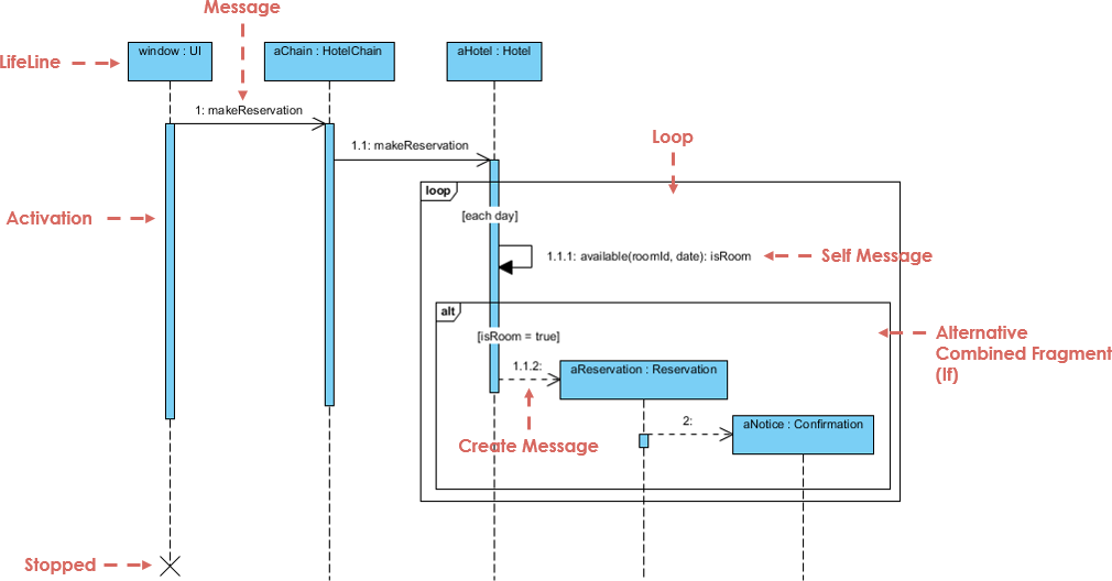
Now, multiple types of UML diagrams will be explained. First, sequence diagrams, they show interactions between objects in a system in a sequential order. The vertical axis of a sequence diagram represents the time at which interactions happen. Sequence diagrams help the documentation and understanding of requirements.
Second, there are class diagrams. This is the most widely used diagram and is the backbone of most object-oriented systems. These diagrams are used to show the classes, their methods and their attributes in a system. This type of diagrams also helps to depict how objects interact.
Third, there are object diagrams. Object diagrams represent the instance of a class diagram and the relationships between these instances. The main benefit of this type of diagrams is that it lets us see the behavior of a system at a particular instant, since we are working with instances and not classes. Object diagrams are closer to the actual behavior of a system than class diagrams.
Fourth, state diagrams, which are used to represent a system or part of it at finite instances of time. They are often called state machines. State diagrams model the dynamic behavior of a class and its response to time and external factors. Not every class of a system is included in a state diagram.
Fifth, let’s talk about package diagrams. Package diagrams show the structure of a system using packages. A package is a namespace used to group elements that are semantically related. This type of diagram shows dependencies between packages. The main benefit is that multiple classes can be grouped into a package, making the diagram easier to read.
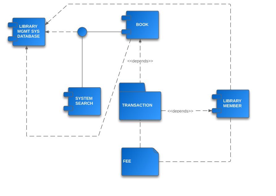
And for the last type of diagrams that will be talked about in this post we have component diagrams. Component diagrams show the relationship between components in a system. A component refers to multiple classes that represent an independent subsystem, the component can act as an interface to the rest of the system. There is a development approach that uses components as its base, Component-Based Development. Since classes are grouped together, this type of diagram allows you to look at the system from a higher level.
After all these types of diagrams, I will briefly cover two concepts, GRASP and MVC. General Responsibility Assignment Software Patterns (GRASP) consist of assigning responsibilities to modules of code. GRASP defines problems and solutions as patterns, these patterns can be applied to your own project. GRASP assigns roles to classes, these roles are: controller, information expert, creator, high cohesion, low coupling, polymorphism and protected classes. Next, there’s the Model-View-Controller Pattern (MVC). A model is an object that carries data. A view is the visualization of the data that the model carries. A controller controls the data flow into a model and updates the view accordingly. A benefit of MVC is simultaneous development, since it is possible to work on the model, view and controller separately.
Thanks to UML, we have a standard way of representing the design of a system. It helps when working with others since, if you use UML, others will be able to understand quickly. Also, there are so many types of diagrams to choose from (even more than the ones that were covered in this post). There will surely be a diagram that fits your needs.
When working in software development, you will often come across the same problems over and over. A design pattern provides a solution for these recurring problems. A design pattern’s main goal is to speed up development by providing well tested solutions. Design patterns, rather than being a block of code, they are a concept of how the problem should be solved, meaning, they are programming language independent. A challenge that commonly arises is knowing which design pattern to use. You will have to know the purpose of design patterns if you want to use them properly. One example of a design pattern are singleton classes, which are classes that there can only be one instance of. These may be needed in cases where there’s only one person in a position, such as the CEO of a company.
Design patterns can be classified into three types. First, creational design patterns which have to do with class instantiation. Here are some examples of these types of patterns:
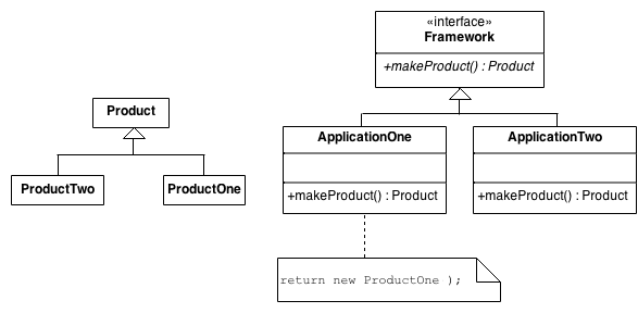
Factory method: an interface for object creation is made, but what actually decides which object is made are its subclasses. It’s like a virtual constructor.
Image source
Object pool: the goal is to reuse objects. When an object is not being used anymore, it gets added to a pool and when a new object needs to be created, one from the pool is selected. This can give a performance boost.
Singleton: already mentioned before, it’s used when a class can only have one instance. A class handles creating, initializing and accessing the instance. The actual instance is a private variable.
Second, there are structural design patterns. These patterns organize classes and objects to create larger structures, inheritance is commonly used for this type. A popular design pattern in this category are adapters. Adapters convert an interface of a class into another interface so it can be used by other programs. It’s similar to the adapters that we use for VGA to HDMI.
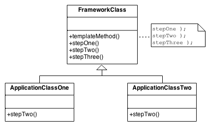
Third, behavioral design patterns. These patterns are all about how objects communicate with each other. An example of this type of design pattern is the template method. This pattern defines only the skeleton of a class and all of its core functions are done by external classes. This way, you can change how a certain step works by only changing one of these external classes.
And on the completely opposite side of the spectrum, we have anti-patterns, which are bad programming practices. While anti-patterns may not seem that useful at first glance, they can help you see whats is a bad practice so you never implement it in the first place. A common anti-pattern in object-oriented design is a god class, which is a class that can do everything. This is not wanted since object-oriented design aims to separate code into smaller parts.
In summary, design patterns help us solve many of the common problems that we face every day as developers. If we apply these to our projects, it will be more efficient and easier to work with. Also, we shouldn’t forget anti-patterns, they can help us see bad practices so we don’t commit them in the first place.
Modeling languages provide a way to express a system, a project or some information using a structure that follows a consistent set of rules for easier understanding. The rules are necessary in order to be able to interpret the language. Modeling languages have been around since the start of the 20th century and are essential to software development.
Many people think of Unified Modeling Language (UML) when they think of modeling languages, but there’s so much more to it than just that. UML was created when several object-oriented modeling languages merged, this means there were quite a few languages before UML. And even to this date, there are some modeling languages that exist independent from UML. The most popular modeling language that isn’t UML is Entity Relationship (ER) and Enhanced Entity Relationship (EER), which are often used when working with databases. The history of modeling languages can be clearly seen thanks to a keynote at Code Generation 2014 by Juha-Pekka Tolvanen.
In this post, I will cover a few modeling languages (not including UML since that will be covered in a later post). First, I will talk about a language that is specifically used in the aerospace industry, Drakon. Its goal is to make procedures easier to understand. Although Drakon was created for the aerospace industry, it has started to see some use outside of it. Drakon has some strict rules such as: only straight lines allowed, no arrows and time in the diagram flows downwards. With these rules, diagrams can become significantly more readable. There’s an IDE to create Drakon flowcharts.
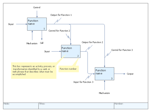
Another modeling language is Integrated Definition (IDEF). It is a graphical process modeling methodology used to express systems. It was developed by the United States Air Force in the 1970s. There are 16 different variations of IDEF, each variation used for different things. Among the many benefits of using IDEF there are: it is usable in every context and industry, easy-to-follow diagrams, gives you a clear overview of the processes, etc. There’s a tool to help you create IDEF diagrams.